The construction of underground cables plays a critical role in ensuring safe, efficient, and long-lasting electrical power transmission. Unlike overhead lines, underground cables are installed below the surface, requiring robust insulation, protective layers, and precise installation techniques to handle both electrical and environmental challenges.
This guide explains the structure of underground cables, includes an underground cable diagram, and describes how these cables are laid and protected in various applications.
1. What Is an Underground Cable?
An underground cable (often called a UG cable) is a type of electrical cable designed to carry power or signals while buried below ground. These cables are specially built to withstand moisture, soil pressure, temperature changes, and mechanical stress.
They are commonly used for:
-
Power distribution in residential and commercial areas
-
Industrial power systems
-
Street lighting and transportation infrastructure
-
Substations and renewable energy installations
2. Basic Construction of Underground Cables
The construction of underground cables consists of multiple layers, each serving a specific purpose for electrical performance, insulation, and protection.
Here’s a breakdown of the typical structure:
(1) Conductor
-
Material: Copper or aluminum
-
Function: Carries the electrical current
-
Types: Solid or stranded depending on flexibility and current capacity
(2) Conductor Shield
-
A semi-conductive layer applied around the conductor
-
Ensures uniform electric field distribution and reduces stress points in insulation
(3) Insulation
-
Material: XLPE (Cross-linked Polyethylene) or EPR (Ethylene Propylene Rubber)
-
Purpose: Electrically isolates the conductor and withstands operating voltage
(4) Insulation Shield
-
Semi-conductive layer covering the insulation to confine the electric field
-
Provides a smooth interface with metallic shielding
(5) Metallic Shield
-
Material: Copper tape, aluminum foil, or wire braid
-
Function: Protects against electromagnetic interference (EMI) and provides a grounding path
(6) Bedding or Inner Sheath
-
Applied over the shielding to hold components together and provide mechanical support
(7) Armoring
-
Material: Steel wire armor (SWA) or steel tape armor (STA)
-
Function: Protects the cable from crushing forces and external mechanical damage
(8) Outer Sheath
-
Material: PVC (Polyvinyl Chloride) or PE (Polyethylene)
-
Function: Provides final protection against moisture, chemicals, and abrasion
3. Underground Cable Construction Diagram
Below is a simplified diagram of underground cable construction:
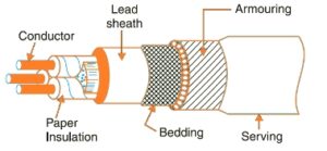
Underground Cable Construction Diagram
Each layer works together to ensure that the underground cable operates safely under voltage stress, environmental exposure, and mechanical pressure.
4. Types of Underground Cables Based on Voltage
The construction of UG cables varies according to voltage level:
| Voltage Class | Typical Cable Type | Insulation Material | Armor Type | Applications |
|---|---|---|---|---|
| Low Voltage (≤1 kV) | PVC or XLPE insulated | PVC/XLPE | Optional | Residential distribution |
| Medium Voltage (1–35 kV) | XLPE insulated, armored | XLPE | SWA or STA | Industrial and urban networks |
| High Voltage (≥35 kV) | XLPE or oil-filled | XLPE or paper-insulated | SWA | Transmission and substations |
5. Underground Cable Laying Methods
Proper laying methods are essential to maintain cable performance and lifespan. Here’s how underground cables are installed:
(1) Direct Burial
-
Cables are laid directly into trenches and covered with sand and protective tiles or warning tape.
-
Most common for LV and MV cables.
(2) Duct System
-
Cables are pulled through underground conduits made of PVC, HDPE, or concrete.
-
Offers easier replacement and maintenance access.
(3) Trough or Tunnel Installation
-
Used for large power transmission cables or areas with multiple circuits.
-
Provides maximum protection and accessibility.
6. Underground Cable Laying Diagram
Below is a typical underground cable laying diagram for direct burial installation:
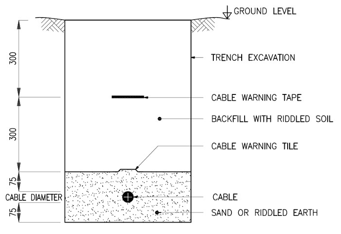
underground cable laying diagram
This design ensures proper mechanical protection, minimizes the risk of accidental digging damage, and provides stable thermal conditions for cable operation.
7. Advantages of Proper UG Cable Construction
-
Enhanced Safety: No exposed conductors or overhead risks
-
Improved Aesthetics: Cables are invisible, keeping environments neat
-
High Reliability: Less affected by weather and external damage
-
Reduced Maintenance: Durable insulation and protection layers
-
Lower Power Loss: Especially in high-voltage XLPE systems
8. Common Materials Used in Underground Cable Construction
| Component | Common Material | Properties |
|---|---|---|
| Conductor | Copper / Aluminum | High conductivity |
| Insulation | XLPE / EPR | Thermal stability, dielectric strength |
| Armor | Steel Wire / Tape | Mechanical protection |
| Outer Sheath | PVC / PE | Moisture and chemical resistance |
9. Maintenance and Fault Detection
While underground systems are durable, proper maintenance is essential.
Typical methods include:
-
Insulation resistance testing (Megger test)
-
Thermal imaging for hot spots
-
Cable sheath integrity tests
-
Time-domain reflectometry (TDR) for fault location
Conclusion
The construction of underground cables combines electrical engineering precision and mechanical strength to ensure reliable power delivery. From conductor selection to proper installation and protection, every element matters in achieving long-term performance.
Understanding UG cable construction and proper laying methods helps engineers design safer, more efficient underground power systems for modern cities and industries.
⚡ Reliable Underground Cables for Every Application
At TOT Wire & Cable, we manufacture and supply a wide range of low-, medium-, and high-voltage underground cables engineered for durability, performance, and safety.
📩 Contact us today for expert recommendations or a free quotation on your underground power project.


