As global data center traffic continues to surge — driven by AI, IoT, and high-definition video streaming — the demand for greater bandwidth and faster interconnects is escalating rapidly. Traditional copper-based electrical links face severe bandwidth limitations at high frequencies due to the skin effect, while optical interconnects, though offering high capacity, require costly components for short-reach, high-density links.
To address these economic and technical challenges, researchers at KAIST (Korea Advanced Institute of Science and Technology) developed an innovative solution: E-TUBE, a metal-cladded dielectric waveguide technology that bridges the gap between electrical and optical interconnects.
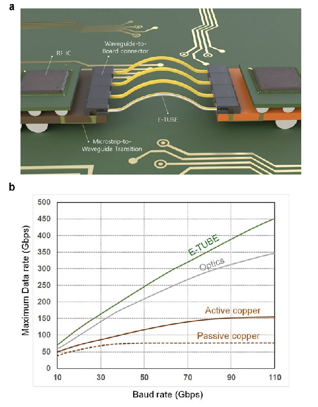
E-TUBE system
E-TUBE Architecture and Performance
E-TUBE Architecture and Performance
The E-TUBE system comprises a metal-cladded dielectric waveguide, microstrip-to-waveguide converters (MWT), board-to-waveguide connectors, and RF transceiver ICs for board-to-board multichannel communication.
E-TUBE demonstrates outstanding performance in throughput-distance product, bending flexibility, and channel density. Compared with conventional waveguides, E-TUBE achieves up to 25 GHz bandwidth at a 70 GHz carrier frequency, with an insertion loss of only 5 dB/m and group delay of 4 ns/m, both frequency-independent — a critical feature for broadband data transmission over extended distances.
Structural Design and Operating Principle
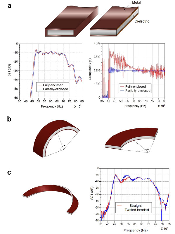
The core innovation of E-TUBE lies in its partially open structure, which differs significantly from traditional fully enclosed metallic waveguides.
E-TUBE uses a 3.5 mm-wide, 0.6 mm-thick dielectric core, coated with thin metallic layers only on its top and bottom surfaces. This unique geometry creates boundary conditions that maintain frequency-independent transmission characteristics across the entire operating band.
Advantages of the Partial Cladding Design
Conventional fully enclosed waveguides confine electromagnetic fields effectively but suffer from frequency-dependent group delay, resulting in channel dispersion and limited throughput-distance product.
In contrast, E-TUBE’s partially cladded design provides constant group delay, enabling higher data rates and longer transmission distances.
Bending Performance
Because of its rectangular shape, E-TUBE supports two primary bending modes:
-
E-plane bending (along the long edge):
The top and bottom metal layers provide sufficient confinement, maintaining negligible performance degradation even at a 5 mm bending radius. -
H-plane bending (along the short edge):
Simulation shows acceptable performance down to a 20 mm radius. Below this, refraction at the air–dielectric boundary increases bending loss and may cause structural deformation.
A 180° twist of the E-TUBE eliminates directional dependency, preserving stable performance under tight bending without mechanical damage.
Material Selection and Loss Optimization
Material Selection and Loss Optimization
The E-TUBE’s superior performance results from meticulous material optimization of both dielectric core and metal cladding.
Dielectric Core Materials
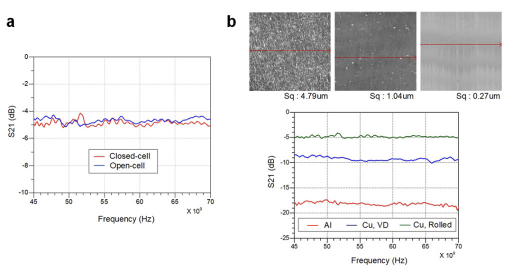
While PTFE is well-known for its low-loss characteristics, its dielectric loss increases sharply above 10 dB/m at 70 GHz, making it unsuitable for multi-meter transmission.
To reduce high-frequency losses, a foamed dielectric is used. Closed-cell foam, with sealed microscopic bubbles, provides better elasticity, flexibility, and dimensional stability than open-cell structures, allowing the core to withstand compression, bending, and twisting during manufacturing.
Metal Cladding Materials
The cladding material directly affects conductor loss, which stems from surface current resistance and roughness-induced scattering.
High-conductivity, smooth-surface metals are essential to minimize ohmic and scattering losses.
Simulation and measurement reveal that copper-cladded E-TUBE outperforms aluminum-cladded versions significantly — achieving up to 9 dB/m lower conductor loss — primarily due to smoother copper surface morphology.
At millimeter-wave frequencies, where skin depth becomes comparable to surface roughness, minimizing roughness is critical to maintaining low propagation loss.
Interface and Integration Design
Interface and Integration Design
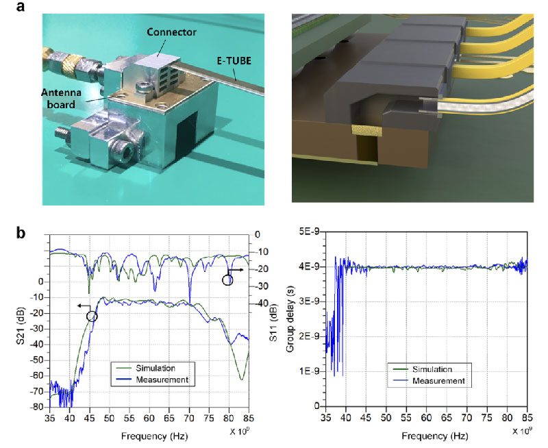
Implementing E-TUBE in practical systems requires precisely engineered interface components to ensure seamless signal transfer between waveguide and PCB.
The interface system includes:
-
Microstrip-to-waveguide converters (MWT): Slot-coupled broadband converters providing smooth transition between planar lines and waveguide modes.
-
Board-to-waveguide connectors: Aluminum connectors with the same dimensions as the E-TUBE core to ensure tight confinement and low reflection.
Measurements confirm stable frequency response from 40 GHz to 85 GHz, with return loss below –10 dB.
Insertion loss scales linearly at 5 dB/m, and group delay remains constant at 4 ns/m, validating the theoretical benefits of the partially cladded design.
System Validation and High-Speed Communication Results
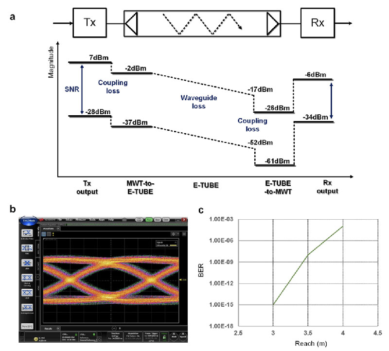
System Validation and High-Speed Communication Results
E-TUBE’s performance was verified using RF transceivers fabricated with standard 28 nm CMOS technology.
At a 70 GHz carrier frequency, the system achieved 25 Gbps NRZ data transmission over a 3 m link with a bit error rate (BER) below 10⁻¹².
Link budget analysis showed an SNR of 28 dB at the receiver output, confirming error-free operation. Eye-diagram measurements displayed clean signal integrity and minimal distortion, proving the low-dispersion characteristics of E-TUBE channels.
Using single-sideband (SSB) modulation, which transmits only the lower sideband, the system doubles spectral efficiency compared to conventional wireless communication.
Application Potential
E-TUBE technology addresses the growing bandwidth demands of modern data centers while offering significant advantages in cost, power efficiency, and manufacturing simplicity compared to optical alternatives.
Its verified performance makes it directly applicable to 100 Gbps and 400 Gbps board-to-board communication, and with advanced modulation schemes, it has the potential to support even higher data rates.
Conclusion
E-TUBE represents a major breakthrough in interconnect technology — combining low loss, wide bandwidth, and mechanical flexibility in a compact, manufacturable form.
By overcoming the inherent limitations of both copper and optical interconnects, it enables scalable, high-throughput links for short- to medium-reach applications such as high-speed computing, AI clusters, and data center backplanes.
With its cost-effective dielectric waveguide design, frequency-independent transmission characteristics, and CMOS-compatible integration, E-TUBE is poised to redefine how next-generation digital systems manage ever-growing data demands — offering a new path toward efficient, scalable, and high-speed communication.


