LXS cable is designed for overhead low voltage power distribution, especially in public utility networks. It is ideal for outdoor installations where cables are suspended between poles or attached to building façades. The cable offers excellent resistance to environmental factors such as UV radiation, temperature changes, and humidity.Parameter
⚠️ Note: LXS cable is not suitable for direct burial or underground installation.
Applications
Public electrical distribution networks
Overhead line installations on poles or facades
Public lighting and auxiliary power supply
Rural and urban low voltage power distribution
Areas with exposure to environmental stress (sunlight, wind, rain)
Its robust design and durable insulation make LXS cable suitable for long-term outdoor service, especially in regions with harsh climates.
Standards
LXS Cable is manufactured in accordance with the following standards:
NP 3528 / HD 626
DMA C33-209
IEC 60754-1 / EN 60754-1 – (Smoke emission characteristics of halogen-free compounds)
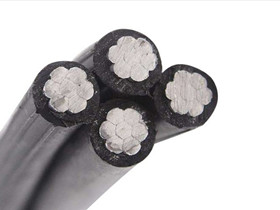
Construction
1. Conductors
Material: Stranded Class 2 Aluminum
Phase conductors and public lighting conductors
Outer stranding direction: Left-hand lay (S)
2. Insulation
Material: Cross-linked Polyethylene (XLPE)
High resistance to mechanical stress, heat, and UV
3. Cable Assembly
Cores are helically laid up
If a messenger wire is included, the phase and auxiliary conductors are stranded around it
Stranding direction: Right-hand lay (Z)
Key Specifications
| Property | Value |
|---|---|
| Operating temperature | -60°C to +50°C |
| Minimum installation temperature | -20°C |
| Continuous permissible conductor temperature | +90°C |
| Overload temperature (≤8 hrs/day) | +130°C |
| Short-circuit temperature (≤5 s) | +250°C |
| Minimum bending radius | 10 × cable diameter |
| Service life | ≥25 years |
Technical Data Table
| Cross Section (mm²) | Nominal Ø (mm) | Weight (kg/km) | Min. Bending Radius (mm) | Max. Current Rating (Air 30°C) |
|---|---|---|---|---|
| 2x16 | 15.0 | 136 | 70 | 85 A |
| 3x16 | 16.0 | 204 | 70 | 75 A |
| 4x16 | 18.0 | 272 | 70 | 75 A |
| 5x16 | 21.0 | 325 | 84 | 75 A |
| 4x25 | 18.5 | 407 | 85 | 97 A |
| 4x25+16 | 19.0 | 475 | 85 | 100 A |
| 4x25+2x16 | 21.0 | 527 | 88 | 100 A |
| 4x35 | 24.7 | 549 | 95 | 120 A |
| 4x35+16 | 26.0 | 612 | 100 | 120 A |
| 4x35+2x16 | 28.0 | 677 | 135 | 120 A |
| 4x50 | 29.5 | 714 | 130 | 150 A |
| 4x50+16 | 30.5 | 782 | 135 | 150 A |
| 4x50+2x16 | 32.0 | 782 | 135 | 150 A |
| 4x70 | 31.0 | 892 | 150 | 190 A |
| 4x70+16 | 33.0 | 1,090 | 160 | 190 A |
| 4x70+2x16 | 35.0 | 1,090 | 160 | 190 A |
| 4x95+16 | 39.0 | 1,404 | 170 | 230 A |
Contact Us for Pricing and Availability
Looking for a reliable LXS cable supplier?
TOT Wire & Cable provides high-quality LXS overhead cables in various sizes, with competitive pricing, fast delivery, and customized packaging.
📩 Contact us today for data sheets, MOQ, or a free quote!