VV Cable Application
– With excellent wear resistance after long use, this is widely used in low voltage circuits of under 0.6/1kV.
VV Cable Standards:
KS C IEC 60502-1
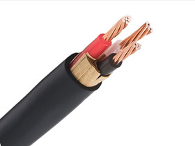
VV Cable Construction
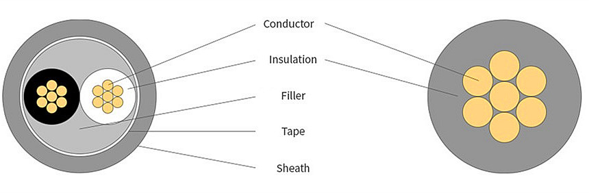
VV Cable Construction
– Conductor : Annealed copper wire for electrical use (circular copper wire, circular compressed copper wire)
– Insulator : Polyvinyl Chloride (PVC)
– Inclusion
– Binder tape
– Wire identification : coloration
– Sheath : Polyvinyl Chloride (PVC)
| Number of inner wires | Color |
| 2 inner wires | Black,White |
| 3 inner wires | Black,White,Red |
| 4 inner wires | Black,White,Red,Green |