Quick Answer
A 3-way switch lets you control one light from two different locations. It requires two 3-way switches connected by traveler wires, allowing either switch to turn the light on or off regardless of the other switch's position.
Basic setup: Power → Switch 1 ↔ Traveler Wires ↔ Switch 2 → Light
3 way switch wiring
What Is a 3-Way Switch?
Simple Explanation
A 3-way switch is a special type of switch that works in pairs to control a single light from two locations. Think of a stairway where you can turn the light on downstairs and off upstairs—that's a 3-way switch system.
Common Locations
- ✅ Stairways (top and bottom control)
- ✅ Hallways (both ends)
- ✅ Large rooms (multiple entry points)
- ✅ Bedrooms (door and bedside)
- ✅ Garages (house door and garage door)
Why It's Called '3-Way'
Common misconception: 'Does it control 3 lights?'
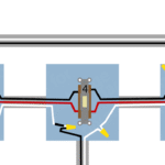
Reality: The switch has 3 terminals (connection points):
- 1 common terminal (darker screw)
- 2 traveler terminals (brass screws)
- Plus 1 ground terminal (green screw)
How to Identify a 3-Way Switch
Visual Differences
| Feature | Regular Switch | 3-Way Switch |
|---|---|---|
| Toggle markings | ON/OFF labeled | No labels |
| Terminal screws | 2 brass screws | 3 screws (1 dark + 2 brass) |
| Can control from 2 locations? | No | Yes |
Terminal Identification
Look at the screws on your switch:
3-Way Switch Terminals:

┌─────────────────┐
│                 │
│  ⚫ Common      │  ← Dark screw (black or darker brass)
│  (darker)       │
│                 │
│  ⚫ Traveler 1  │  ← Brass screw
│                 │
│  ⚫ Traveler 2  │  ← Brass screw
│                 │
│  🟢 Ground      │  ← Green screw
│                 │
└─────────────────┘
Quick check: If your switch has no ON/OFF markings and has one darker screw plus two lighter screws, it's a 3-way switch.
Understanding Wire Colors
Standard Wire Colors
| Color | Purpose | Memory Trick |
|---|---|---|
| Black | Hot wire (power) | 'Black = power back' |
| White | Neutral wire | 'White = light' |
| Red | Traveler wire | 'Red = road between switches' |
| Green/Bare | Ground wire | 'Green = ground (like grass)' |
Important: In 3-way circuits, white wires sometimes carry power and must be marked with black tape.
Wire Gauge for 3-Way Switches
- Lighting circuits: Use 14/3 Romex (white jacket) on 15-amp circuit
- Heavy loads or longer runs: Use 12/3 Romex (yellow jacket) on 20-amp circuit
The '/3' means three conductors (black, white, red) plus ground—exactly what you need for 3-way switching.
Configuration 1: Power at Switch (Most Common)
When You'll See This
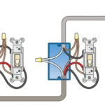
This is the most common and easiest configuration. The power comes into the first switch box, travels to the second switch, then goes to the light.
Wiring Diagram
Power Source → Switch 1 → Travelers → Switch 2 → Light Fixture

[Power Panel]
    ↓
[Switch Box 1]
    ║ (Travelers)
    ║
[Switch Box 2]
    ↓
[Light Fixture]
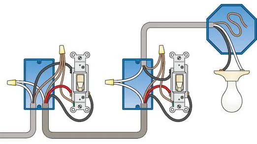
Wire Connections
At Switch 1 (Power Source):
Power cable (14/2):           3-wire cable to Switch 2 (14/3):
- Black (hot) ────────────→   Common terminal (dark screw)
- White (neutral) ─────────→  Wire nut with white from Switch 2 cable
- Ground ──────────────────→  Ground screw + ground to Switch 2

From Switch 1 to Switch 2:
- Red wire ────────────────→  Traveler terminal (brass screw)
- Black wire ──────────────→  Traveler terminal (brass screw)
At Switch 2:
3-wire cable from Switch 1:   Cable to light (14/2):
- Red wire ───────────────→   Traveler terminal (brass screw)
- Black wire ─────────────→   Traveler terminal (brass screw)
- White (neutral) ────────→   Wire nut with white to light
- Ground ─────────────────→   Ground screw + ground to light

To light fixture:
- Black from common terminal → Black wire to light
At Light Fixture:
- Black from Switch 2 → Black wire on fixture
- White (neutral) → White wire on fixture
- Ground → Ground on fixture
Step-by-Step Installation
Step 1: Turn Off Power ⚠️
CRITICAL SAFETY:
- Turn off breaker for the circuit
- Test with voltage tester at switch box
- Test again to confirm no power
- Tape breaker in OFF position
Step 2: Wire First Switch (Power Source)
- Incoming black wire (hot) → Common terminal (dark screw)
- This brings power into the switch
- Red traveler wire → One brass screw
- Goes to second switch
- Black traveler wire → Other brass screw
- Goes to second switch
- Ground wire → Green ground screw
- White wires → Connect together with wire nut
- Neutral passes through to second switch
Step 3: Wire Second Switch
- Red traveler wire → One brass screw
- Comes from first switch
- Black traveler wire → Other brass screw
- Comes from first switch
- Black wire to light → Common terminal (dark screw)
- This sends switched power to light
- Ground wire → Green ground screw
- White wires → Connect together with wire nut
- Neutral passes through to light
Step 4: Connect Light Fixture
- Black wire from switch → Black fixture wire
- White neutral → White fixture wire
- Ground → Ground fixture wire
Step 5: Test
- ✅ Restore power at breaker
- ✅ Test switch 1 (on/off)
- ✅ Test switch 2 (on/off)
- ✅ Verify both switches control the light
Configuration 2: Power at Light
When You'll See This
In older homes or when the light fixture is on the main circuit and switches were added later, power enters at the light fixture first.
Key Difference
⚠️ Important: In this configuration, white wires between switches carry power and MUST be marked with black electrical tape at both ends.
Wiring Diagram
Power Source → Light Fixture → Switch 1 ↔ Switch 2

[Power Panel]
    ↓
[Light Fixture]
    ║
[Switch 1]
    ║ (Travelers)
    ║
[Switch 2]
Wire Connections
At Light Fixture:
Power cable:                  3-wire cable to Switch 1:
- Black (hot) ────────────→   White wire (mark with black tape!)
- White (neutral) ────────→   Wire nut with:
                               - White from fixture
                               - Black from Switch 1 cable
- Ground ──────────────────→  Ground to fixture + ground to Switch 1
At Switch 1:
- White wire (marked black) → Common terminal (dark screw)
- Red traveler → Brass screw
- Black traveler → Brass screw
- Ground → Ground screw
At Switch 2:
- White wire (marked black) → Common terminal (dark screw)
- Red traveler → Brass screw
- Black traveler → Brass screw
- Ground → Ground screw
Critical Safety Note
🚨 WHITE WIRES CARRY POWER IN THIS SETUP
Always mark white wires that carry power:
- Wrap black electrical tape around both ends
- This warns others: 'This white wire is hot!'
- Required by electrical code
- Prevents dangerous mistakes during future work
Adding a 4-Way Switch (Three Locations)
When You Need This
Want to control one light from three or more locations? You need to add 4-way switches between two 3-way switches.
Examples:
- Long hallway with three doorways
- Large room with three entrances
- Three-story stairway
How It Works
3-Way Switch → 4-Way Switch → 3-Way Switch → Light
  (First)       (Middle)        (Last)
You can add multiple 4-way switches for even more control locations.
4-Way Switch Terminals
A 4-way switch has 4 brass terminals (no common terminal):
- 2 terminals labeled 'Input' or 'Line'
- 2 terminals labeled 'Output' or 'Load'
Wiring a 4-Way Switch
The simple rule: 4-way switches are 'pass-through' switches placed between two 3-way switches.
Connections:
From 3-Way Switch 1:          To 3-Way Switch 2:
- Traveler 1 (red) ──────→    Input terminal 1
                              Output terminal 1 ──────→ Traveler 1 (red)

- Traveler 2 (black) ────→    Input terminal 2
                              Output terminal 2 ──────→ Traveler 2 (black)
Installation Steps
- Wire the first 3-way switch (power source) as normal
- Run travelers to the 4-way switch
- Connect travelers to input terminals on 4-way
- Run new travelers from output terminals to second 3-way switch
- Wire the second 3-way switch (to light) as normal
Pro tip: Label all wires before disconnecting anything. Take photos for reference.
Tools and Materials Needed
Essential Tools
- [ ] Voltage tester (non-contact type recommended)
- [ ] Screwdrivers (Phillips and flat-head)
- [ ] Wire strippers (for 14-16 AWG)
- [ ] Needle-nose pliers
- [ ] Flashlight or headlamp
Materials
- [ ] 3-way switches (2 minimum)
- [ ] Wire nuts (appropriate size for connections)
- [ ] Electrical tape (black)
- [ ] 14/3 or 12/3 Romex cable (as needed)
- [ ] Cable staples (for securing Romex)
Optional but Helpful
- Wire labels or colored tape
- Cable pulling lubricant (for long runs)
- Junction box (if needed)
- Cover plates
Common Problems and Solutions
Problem 1: Light Doesn't Work at All
Check these items:
□ Power is on
- Verify breaker is on
- Test voltage at switch box
- Check if other outlets on circuit work
□ Light bulb works
- Try bulb in another fixture
- Check if bulb is fully screwed in
□ Common terminal wired correctly
- Black wire from power goes to common on first switch
- Black wire to light goes to common on second switch
□ All connections are tight
- Check all wire nuts
- Tighten all terminal screws
Problem 2: Works from One Switch Only
This means: Traveler wires are incorrect.
Quick fix:
- Turn off power
- At either switch, swap the two traveler wires (on brass screws)
- Restore power and test
Why this works: The travelers can be connected to either brass screw—if only one position works, they're likely reversed at one switch.
Problem 3: Light Stays On Constantly
Possible causes:
□ Switches wired as single-pole
- Verify common terminals are used correctly
- Check that travelers go to brass screws
□ Wrong switch type
- Confirm both switches are 3-way switches
- Look for 3 terminals (plus ground) on each switch
Problem 4: Flickering or Intermittent Operation
Check for:
□ Loose connections
- Tighten all terminal screws
- Remake all wire nut connections
□ Damaged wire
- Inspect all wires for nicks or damage
- Replace damaged cable sections
□ Bad switch
- Test switch with multimeter
- Replace if switch is faulty
Problem 5: After Adding 4-Way Switch
If light doesn't work:
□ Verify 4-way switch orientation
- Input terminals connect to first 3-way
- Output terminals connect to second 3-way
- Some 4-way switches work either way, some don't
□ Check traveler continuity
- Travelers must run continuously from 3-way to 4-way to 3-way
- No breaks or incorrect connections
Safety Guidelines
Before You Start
⚠️ CRITICAL SAFETY RULES:
- Always turn off power at the breaker
- Never just flip the switch off
- Lock out breaker if possible
- Tape breaker in OFF position
- Test for voltage before touching wires
- Use a voltage tester
- Test multiple times
- Assume wires are live until proven otherwise
- Work in good lighting
- Use flashlight or work light
- See what you're doing clearly
- Wear safety glasses
- Protect eyes from wire ends
- Prevents debris falling into eyes
During Installation
✅ Best practices:
- Connect ground wires first (creates safety path)
- Strip only enough insulation (3/4 inch maximum)
- Twist wires before adding wire nuts
- Tug-test all connections
- Keep wire nuts tight
- No bare wire exposed outside connections
- Use appropriate wire nuts for wire gauge
When to Call a Professional
Consider hiring an electrician if:
- You're not comfortable working with electricity
- Wires are old, brittle, or damaged
- You don't have the proper tools
- Local code requires licensed work
- You smell burning or see sparks
- Situation is more complex than expected
Typical cost: $150-300 per switch installation
Code Requirements
National Electrical Code (NEC) Basics
Key requirements for 3-way switches:
✅ Wire sizing:
- 14 AWG minimum for 15-amp circuits
- 12 AWG minimum for 20-amp circuits
- Match wire gauge to breaker size
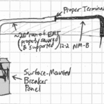
✅ Cable protection:
- Romex must be secured every 4.5 feet
- Secure within 12 inches of boxes
- Protect from physical damage
✅ Box fill:
- Don't overfill junction boxes
- Follow NEC Chapter 9 Table 1
- Count switches, devices, and wire nuts
✅ Grounding:
- All switches must be grounded
- Ground wires must be continuous
- Metal boxes must be grounded
✅ Marking hot neutrals:
- White wires carrying power must be marked
- Use black tape or paint
- Required at both ends
Local Codes
Important: Local codes may be stricter than NEC.
- Some areas require permits for switch changes
- Some require licensed electrician for all work
- Some require inspection of electrical work
- Always check with local building department
Choosing the Right Switches
Switch Quality Levels
Budget ($2-5):
- Basic functionality
- Shorter lifespan (5-10 years)
- May feel loose over time
- Fine for low-use locations
Mid-Range ($5-12):
- Better build quality
- Longer lifespan (10-15 years)
- Smoother operation
- Good for most applications
Premium ($12-25):
- Commercial-grade quality
- Very long lifespan (15-25+ years)
- Quieter operation
- Best for high-use locations
Switch Specifications
Amperage rating:
- 15-amp: Standard for most residential
- 20-amp: Commercial or heavy-duty
- Match or exceed circuit breaker rating
Voltage rating:
- 120V: Standard residential
- 120-277V: Can handle commercial voltages
Wire terminations:
- Screw terminals: Most common, very reliable
- Back-wire (push-in): Faster but less reliable
- Side-wired: Best for solid core wire
Special Features
Available options:
- Lighted switches: Small LED shows switch location in dark
- Quiet switches: Reduced click noise
- Commercial grade: Heavy-duty construction
- Tamper-resistant: Covered screws for security
Note: Smart switches and dimmers require different wiring—see separate guides for those installations.
Tips for Success
Planning Your Installation
📋 Before you start:
- Map your circuit
- Identify which breaker controls the circuit
- Note all affected lights/outlets
- Sketch wire routing
- Measure cable runs
- Add 20% extra length for connections
- Account for obstacles and turns
- Plan shortest, most direct path
- Gather all materials first
- Don't start without everything needed
- Have spare wire nuts and tape
- Extra wire is better than running short
Installation Best Practices
💡 Pro tips:
- Label everything
- Mark wires before disconnecting
- Use colored tape or labels
- Take photos of existing wiring
- Work cleanly
- Strip wires to consistent length (3/4')
- Make neat, tight connections
- Coil excess wire neatly in box
- Test as you go
- Verify connections before closing box
- Test with voltage tester
- Check switch operation both locations
- Use wire nuts properly
- Match size to number/gauge of wires
- Twist wires clockwise first
- Wire nut should be snug, not loose
- Tug-test every connection
- Ground everything
- Connect ground first, disconnect last
- Pigtail if needed for multiple connections
- Never leave grounds disconnected
Common Mistakes to Avoid
❌ Don't do this:
- Working with power on
- Recipe for shock or electrocution
- Always turn off breaker first
- Using wrong wire size
- Must match or exceed breaker rating
- 15A breaker = 14 AWG minimum
- 20A breaker = 12 AWG minimum
- Forgetting to mark hot neutrals
- White wires carrying power must be marked
- Use black tape at both ends
- Code requirement in power-at-light config
- Overfilling boxes
- Too many wires creates heat buildup
- Difficult to close box safely
- Use larger box or junction box
- Mixing wire gauges
- Don't splice 14 AWG to 12 AWG in circuit
- Smallest wire determines breaker size
- Use consistent gauge throughout
Frequently Asked Questions
Can I use a dimmer with 3-way switches?
Yes, but you need a special 3-way dimmer. Install the dimmer at one location and a regular 3-way switch at the other. Standard dimmers won't work in 3-way applications.
Do the traveler wires have to be specific colors?
No. While red and black are standard, travelers can be any color except white or green. The key is that they connect the two brass terminals on each switch.
Can I control more than one light?
Yes. Multiple light fixtures can be wired in parallel on the same 3-way circuit. All lights will be controlled together by both switches.
What if I have 4 wires plus ground?
You likely have a 4-wire cable (14/4 or 12/4). This is sometimes used but not necessary. You only need 3 conductors plus ground for 3-way switching. Cap the extra wire with a wire nut.
Why does my light dim when I use one switch?
This suggests loose connections or high resistance. Turn off power and check all connections. Tighten terminal screws and remake wire nut connections.
Can I replace one 3-way switch with a smart switch?
Yes, but you typically need a smart 3-way switch kit. Most smart switches require a neutral wire and special companion switches. Check manufacturer instructions carefully.
Do I need an electrician or can I DIY this?
In most areas, homeowners can legally do electrical work in their own homes. However, you must:
- Follow all local codes
- Get required permits
- Have work inspected if required
- Be comfortable working safely with electricity
If you're uncertain, hire a licensed electrician.
Conclusion
Wiring 3-way switches is a manageable DIY project with proper planning and attention to safety. The key points to remember:
Essential steps:
- ✅ Always turn off power and test before working
- ✅ Identify common and traveler terminals correctly
- ✅ Use proper wire colors and mark hot neutrals
- ✅ Make tight, secure connections
- ✅ Test thoroughly before closing boxes
Most important: If you're ever unsure or uncomfortable, stop and call a licensed electrician. Electrical work can be dangerous if done incorrectly, and professional installation is always the safest choice.
Related Articles: