Understanding how electrical outlets are wired is essential for any homeowner, DIY enthusiast, or electrical apprentice. Whether you’re replacing an old outlet or adding a new one, learning the basics of house electrical outlet wiring ensures safety, code compliance, and functionality.
This guide explains outlet wiring using simple terms, step-by-step visuals, and a basic wiring diagram to help beginners get started.
What is an Electrical Outlet Wiring Diagram?
A basic outlet wiring diagram shows how electrical wires connect to a standard wall receptacle (outlet). It includes the hot wire (live), neutral wire, and ground wire. These diagrams are invaluable for:
Safe DIY electrical repairs
Planning small home renovations
Understanding home electrical systems
Parts of a Standard Outlet
Before we get into the wiring diagram, here’s what you need to know about a standard 120V outlet in North America:
Hot (Live) Wire: Carries electricity to the outlet (usually black or red)
Neutral Wire: Completes the circuit and carries current back (usually white)
Ground Wire: Provides safety and prevents shock (usually bare copper or green)
Basic Tools You’ll Need
To wire a basic electrical outlet safely, you’ll need:
Voltage tester or multimeter
Screwdriver (flathead & Phillips)
Wire stripper
Electrical tape
Needle-nose pliers
New outlet and outlet box (if installing from scratch)
Basic Electrical Outlet Wiring Diagram
Here’s a simplified outlet wiring diagram:
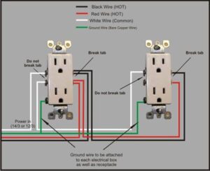
simplified outlet wiring diagram
Legend:
Brass screw connects to the hot (black) wire.
Silver screw connects to the neutral (white) wire.
Green screw connects to the ground (bare/green) wire.
Step-by-Step: How to Wire a Basic Outlet
1. Turn Off Power
Always turn off the power at the circuit breaker before doing any wiring. Use a voltage tester to confirm no power is present.
2. Prepare the Wires
Strip about ¾ inch of insulation from the end of each wire.
3. Connect the Wires
Black wire (hot) to the brass screw
White wire (neutral) to the silver screw
Bare/green wire (ground) to the green screw
Loop the wire clockwise around the screw and tighten firmly.
4. Secure the Outlet
Gently fold the wires back into the box and mount the outlet securely using screws.
5. Install Cover Plate and Restore Power
Once installed, screw on the outlet cover plate. Turn the circuit breaker back on and test the outlet using a plug-in tester or appliance.
Tips for Safe DIY Wiring
Always check local electrical code requirements.
Use GFCI outlets in bathrooms, kitchens, garages, and outdoor locations.
Never connect more than one circuit to a single outlet.
If you’re unsure, consult a licensed electrician.
Common Outlet Wiring Variations
| Type of Wiring | Description |
|---|---|
| Backstabbing | Inserting wires into holes at the back of the outlet — not recommended due to loose connections over time. |
| Daisy Chaining | Connecting multiple outlets in a series using pigtails or terminal screws. |
| Split Receptacles | Allows top and bottom outlets to operate independently (often used for switched outlets). |
When to Use a GFCI or AFCI Outlet
GFCI (Ground Fault Circuit Interrupter): Protects against electric shock in wet areas.
AFCI (Arc Fault Circuit Interrupter): Prevents fires caused by arcing faults in bedrooms and living spaces.
Modern codes often require these protection devices for new or renovated circuits.
Conclusion
Understanding a basic house electrical outlet wiring diagram empowers you to make safer decisions when dealing with your home’s electrical system. While simple projects like replacing an outlet are manageable, always prioritize safety and know when to call in a professional.