An electrical wiring diagram for a house is a schematic blueprint that illustrates how electrical circuits, components, and systems are interconnected within a residential building. These diagrams are critical for safe, efficient installations, renovations, and troubleshooting. Whether you're a homeowner, electrician, or contractor, understanding wiring diagrams is key to ensuring code-compliant and reliable electrical systems.

electrical wiring diagram house
Types of House Electrical Wiring Diagrams
1. Schematic Diagrams
Schematic diagrams focus on the logic of electrical connections using standardized symbols. They are ideal for diagnosing circuit behavior and troubleshooting issues.
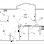
2. Layout Diagrams (Pictorial)
These diagrams represent the physical layout of components within a house, showing where outlets, switches, and fixtures are installed in relation to architectural features.
3. Single-Line Diagrams
Used to depict the overall electrical distribution, these diagrams show a simplified connection between the main panel, sub-panels, and major circuits.
4. Circuit Diagrams
These focus on individual circuits, showing connections between switches, outlets, lights, and other components.
Essential Components in House Wiring Diagrams
Main Service Panel
The central hub distributing power from the utility to all branch circuits. Diagrams show how breakers are wired and how electricity flows to different zones.
Branch Circuits
Circuits that serve different sections or appliances in the house:
- Lighting circuits (15A)
- Outlet circuits (20A)
- Dedicated kitchen and bathroom circuits (often with GFCI protection)
- Heavy-duty appliance circuits (e.g., HVAC, oven)
Grounding System
Provides a safe path for fault current. Includes ground rods, conductors, and bonding points. Essential for fire prevention and shock protection.
Protection Devices
- Circuit Breakers: Prevent overloads and short circuits
- GFCIs: Protect against ground faults in wet areas
- AFCIs: Detect arc faults to prevent fires
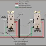
Common Electrical Symbols
Basic Symbols
- Outlet: Circle or rectangle with lines
- Switch: 'S' with a slash or toggle
- Light Fixture: Circle with cross
- Wire Connection: Dot at intersection
Special Symbols
- GFCI: Marked outlet symbol with 'GFCI'
- 3-Way Switch: 'S3' or double toggle symbol
- Ground: Triangle pointing downward
- Smoke Detector: Circle with 'SD'
Creating and Reading Diagrams
Planning Phase
- Load Calculation: Estimate total consumption
- Compliance: Follow NEC and local codes
- Future-Proofing: Plan for potential upgrades
Design Process
- Start with a floor plan
- Plan circuits per zone/load
- Place components based on usage and accessibility
- Route wires through walls, ceilings, and safe zones
Documentation Standards
- Consistent symbols and labels
- Include legends and revision tracking
- Clearly show wire types and sizes
Reading Tips
- Trace from the main panel
- Identify loads and switches
- Check wire sizing and color coding
Key House Circuits and Best Practices
Lighting Circuits
- Use 15A breakers with 14 AWG wire
- Include 3-way or 4-way switches for large spaces
Kitchen Circuits
- Two 20A circuits for countertop outlets
- Separate circuits for fridge, microwave, dishwasher
Bathroom Circuits
- 20A GFCI-protected circuit for outlets
- Separate lighting and ventilation circuits
Appliance Circuits
- Use appropriate gauge wire (e.g., 10 AWG for dryers)
- Use 240V circuits for heavy loads
Smart Home & Modern Considerations
Smart Devices
- Require neutral wires
- Compatible loads must be verified
Home Automation
- Plan low-voltage wiring (intercom, cameras)
- Provide space and power for hubs and control panels
Maintenance and Updates
Keep Diagrams Current
- Update after renovations or new installations
- Store both digital and hard copies
Upgrade Planning
- Revise diagrams when panels or circuits change
- Include new code updates
DIY vs Professional Work
Hire Professionals For:
- Main service and panel upgrades
- High-voltage circuits
- Work requiring permits and inspections
DIY Tips:
- Learn local and NEC codes
- Use proper tools and test procedures
- Always turn off power before working
Conclusion
House electrical wiring diagrams are vital tools for designing, installing, maintaining, and upgrading residential electrical systems. Whether you're tackling a DIY project or working with licensed electricians, a clear and accurate diagram ensures safety, code compliance, and system reliability.
Understanding wiring layouts, circuit types, protection requirements, and modern smart integrations empowers homeowners and professionals alike to make informed decisions. When in doubt, always consult a certified electrician to avoid hazards and ensure long-term electrical performance.