When working on Polaris ATVs or snowmobiles (Sportsman, RZR, General, etc.), understanding their proprietary wire color codes is essential for troubleshooting, repairs, or accessory installations.
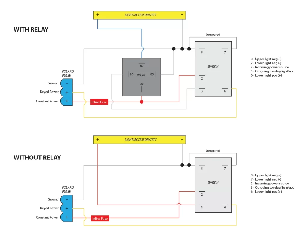
polaris wire color code
🧩 Common Polaris Wire Colors & Meanings
Source: Vintage Polaris electrical diagram vintagesnow
BLU / Blue – Switched power or lighting circuits
BLU/W (Blue w/ White tracer) – Accessory circuits or tail lights
BLU/GRN – Secondary accessory or sensor circuits
BRN / Brown – Ground or negative reference
BRN/R (Brown w/ Red) – Sensor ground or ignition switch
GRY / Gray – Neutral switch or indicator circuits (e.g., alert lamps)
GRN / Green – Power from stator or real-time switched outputs
GRN/W (Green w/ White) – Fuel level, coolant temp, or speedometer sensors
LG / Light Green – Tachometer or GPS signal
LG/BLK (Light Green w/ Black) – ECU or CDI signal input
OR / Orange – Kill switch or prime circuit
OR/BLK – Starter relay or engine-on command
P/BLU (Pink w/ Blue) – Headlight high-beam
R/GRN (Red w/ Green) – Fuse/battery hot feed
Y/BLU (Yellow w/ Blue) – Charge lamp or voltage regulator
Y/GRN – ECU switched-on input
🔌 Solid colors are main conductors; tracer colors indicate secondary pathways or sensor lines.
📌 Real-World Examples
Brown is commonly used for chassis or circuit ground
Yellow (Y/BLU) from the regulator signals the charge lamp.
Polaris electrical manuals (e.g. 1996–1998 snowmobile and 2007 Sportsman 500) showcase these color conventions .
🛠 How to Use This Color Guide Effectively
Confirm by reference: Always check your model's specific wiring diagram. These codes often match original Polaris manuals.
Label before disconnecting: Especially for tracer wires—document both main and stripe colors.
Test before replacing: Use a multimeter to verify live voltage, ground continuity, or sensor signal.
Referencing forums: DIYers frequently note Brown = ground or Yellow = stator line
🛡 Why This Matters
Correct color decoding prevents miswiring damage to key components like CDI, ECU, or stator.
Many Polaris models share common wiring across multiple years—spot wiring issues reliably using this reference chart.
✅ Quick Reference Table
| Color | Typical Purpose |
|---|---|
| Blue | Main switched power or lighting circuits |
| Blue/White, Blue/Green | Accessories or tail light feeds |
| Brown | Ground/negative rails |
| Gray | Sensor/neutral detection |
| Green variants | Sensor input (e.g. tachometer, speedometer) |
| Orange | Kill switch or engine-off circuitry |
| Orange/Black | Starter or key 'on' circuit |
| Pink/Blue | High-beam light activation |
| Red/Green | Battery hot fused feed |
| Yellow/Blue | Charge indicator or voltage regulator output |
| Yellow/Green | ECU or switched-on signal |

