Shielded instrumentation cable forms the backbone of modern industrial control and monitoring systems, providing reliable signal transmission in challenging electromagnetic environments. As industrial facilities become increasingly sophisticated with advanced automation systems, process control equipment, and digital communication networks, the importance of selecting the right shielded instrumentation cable cannot be overstated. This comprehensive guide explores everything you need to know about shielded instrumentation cables, from basic construction principles to advanced application considerations.
Shielded Instrumentation Cable
What is Shielded Instrumentation Cable?
Shielded instrumentation cable is a specialized type of electrical cable designed to transmit low-level signals between instruments, sensors, controllers, and monitoring equipment while protecting these signals from electromagnetic interference (EMI) and radio frequency interference (RFI). The key distinguishing feature is the metallic shield that surrounds the signal conductors, providing a barrier against external electromagnetic fields that could corrupt critical measurement and control data.
Unlike standard power cables that carry high voltages and currents, shielded instrumentation cable is engineered specifically for signal integrity, featuring:
- Low-voltage signal transmission (typically 0-10V, 4-20mA, or digital signals)
- Precision conductor arrangements (twisted pairs, triads, or quads)
- Specialized insulation materials optimized for signal clarity
- Electromagnetic shielding to prevent interference
- Flexible construction suitable for various installation methods
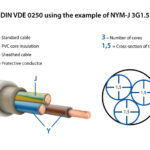
Construction Elements of Shielded Instrumentation Cable
Understanding the construction of shielded instrumentation cable is essential for proper selection and application:
Conductor Materials and Configuration
The conductors in shielded instrumentation cable are typically made from:
- Tinned copper: Most common, providing excellent conductivity and corrosion resistance
- Bare copper: For applications where tinning is not required
- Special alloys: For thermocouple extension cables requiring specific thermal characteristics
Common conductor configurations include:
- Twisted pairs: Two conductors twisted together to reduce electromagnetic pickup
- Triads: Three conductors twisted together for balanced signal transmission
- Quads: Four conductors in a star configuration for maximum noise rejection
- Multiple pairs: Several twisted pairs within a single cable
Insulation Materials
Shielded instrumentation cable insulation materials are selected based on application requirements:
- PVC (Polyvinyl Chloride): Cost-effective for general-purpose applications
- PE (Polyethylene): Better electrical properties and moisture resistance
- XLPE (Cross-Linked Polyethylene): Enhanced temperature and chemical resistance
- FEP/PTFE (Fluoropolymers): High-temperature applications up to 200°C
- Polyolefin: Low-smoke, zero-halogen options for safety-critical installations
Shielding Types and Configurations
The shield is the most critical component of shielded instrumentation cable:
Foil Shielding
- Aluminum/polyester tape: 100% coverage, lightweight, cost-effective
- Excellent high-frequency protection: Effective against EMI/RFI
- Drain wire included: Facilitates easy grounding connections
- Applications: Process control, data acquisition, building automation
Braided Shielding
- Tinned copper braid: 85-95% coverage, excellent flexibility
- Superior mechanical protection: Withstands vibration and movement
- Lower electrical resistance: Better grounding path than foil
- Applications: Motor control, servo systems, dynamic installations
Combination Shielding
- Foil plus braid: Maximum protection combining both shield types
- 100% coverage with flexibility: Optimal for critical applications
- Enhanced durability: Superior mechanical and electrical protection
- Applications: Precision measurement, critical control systems
Spiral Shielding
- Helical tape wrap: Good coverage with moderate flexibility
- Cost-effective solution: Between foil and braid in performance and cost
- Uniform protection: Consistent coverage along cable length
- Applications: General industrial instrumentation
Individual vs. Overall Shielding
Shielded instrumentation cable can feature different shielding architectures:
Individual Shielded Pairs (ISP)
- Each pair has its own shield: Maximum crosstalk prevention
- Superior signal isolation: Ideal for multiple signal types in one cable
- Higher cost: More complex manufacturing process
- Applications: Multi-channel measurement systems, complex control panels
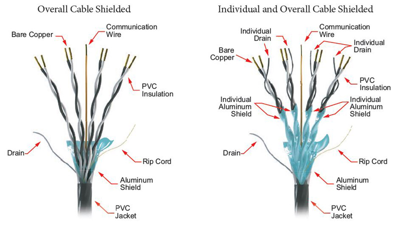
Overall Shielded (OS)
- Single shield around all conductors: Cost-effective for most applications
- Simpler termination: Easier installation and maintenance
- Good general protection: Adequate for most industrial environments
- Applications: Single-function cables, simple control circuits
Individual and Overall Shielded (I/OS)
- Maximum protection: Both individual and overall shields
- Ultimate signal integrity: Best performance in high-noise environments
- Premium cost: Justified for critical applications only
- Applications: Precision instrumentation, safety-critical systems
Types of Shielded Instrumentation Cables
Different applications require specific types of shielded instrumentation cable:
Twisted Pair Shielded Instrumentation Cable
The most common type, featuring twisted conductor pairs:
- Standard configurations: 1, 2, 3, 4, 6, 8, 12, or more pairs
- AWG sizes: Typically 16, 18, 20, 22, or 24 AWG
- Applications: Analog signal transmission, RTD connections, digital I/O
- Industries: Process control, manufacturing, building automation
Multi-Conductor Shielded Control Cable
Designed for complex control systems:
- Multiple individual conductors: 4, 6, 8, 12, 16, 20, or more conductors
- Color-coded identification: Easy conductor identification during installation
- Applications: PLC connections, motor control, panel wiring
- Features: Overall shield with drain wire for easy grounding
Thermocouple Extension Cable
Specialized shielded instrumentation cable for temperature measurement:
- Matched conductor materials: Specific alloys for each thermocouple type
- Color-coded jackets: ANSI/IEC standard color identification
- Types available: J, K, T, E, N, R, S, and B thermocouples
- Applications: Temperature monitoring, process control, HVAC systems
Computer and Data Cable
For digital communication and computer interfaces:
- Impedance controlled: Specific characteristic impedance (typically 120Ω)
- Low capacitance: Minimizes signal distortion
- Applications: RS-485, RS-232, Ethernet, fieldbus communications
- Standards compliance: EIA/TIA, IEEE, and industry-specific standards
Tray Cable (TC)
Heavy-duty shielded instrumentation cable for industrial environments:
- Multiple conductor options: Power and control conductors in one cable
- Flame-resistant jackets: Meeting NEC requirements for tray installation
- Applications: Industrial control panels, motor control centers
- Installation: Cable tray, conduit, or direct burial applications
Armored Instrumentation Cable
For harsh environments requiring mechanical protection:
- Steel wire armor: Protection against rodents and mechanical damage
- Interlocked armor: Flexibility with mechanical protection
- Applications: Direct burial, hazardous locations, marine environments
- Ratings: Available in various voltage and temperature ratings
Application Areas for Shielded Instrumentation Cable
Shielded instrumentation cable finds applications across numerous industries:
Process Control and Manufacturing
- Analog signal loops: 4-20mA transmitter connections
- Temperature monitoring: RTD and thermocouple circuits
- Pressure and flow measurement: Transducer and transmitter wiring
- Control valve operation: Positioner and actuator connections
- Safety instrumented systems: Critical shutdown and alarm circuits
Building Automation and HVAC
- Temperature control: Room sensors and thermostats
- Humidity monitoring: Relative humidity sensors
- Air quality measurement: CO2, VOC, and particulate sensors
- Lighting control: Dimming and occupancy sensor circuits
- Fire safety systems: Smoke detectors and notification circuits
Power Generation and Utilities
- Generator monitoring: Vibration, temperature, and performance sensors
- Switchgear instrumentation: Voltage, current, and power measurements
- Substation control: SCADA and protection system communications
- Renewable energy: Solar and wind farm monitoring systems
- Smart grid applications: Advanced metering infrastructure
Oil, Gas, and Petrochemical
- Pipeline monitoring: Pressure, flow, and leak detection systems
- Tank level measurement: Radar, ultrasonic, and pressure sensors
- Gas detection: Combustible and toxic gas monitoring
- Wellhead instrumentation: Downhole monitoring and control
- Refinery process control: Complex multi-variable control systems
Marine and Offshore
- Navigation systems: GPS, radar, and sonar equipment
- Engine monitoring: Temperature, pressure, and performance sensors
- Ballast tank monitoring: Level and pressure measurement
- Safety systems: Fire detection and suppression controls
- Communication systems: VHF, satellite, and internal communications
Transportation and Automotive
- Railway signaling: Track circuits and signal control
- Traffic management: Intersection control and monitoring
- Vehicle instrumentation: Engine and performance monitoring
- Electric vehicle charging: Control and monitoring systems
- Airport ground support: Aircraft servicing equipment
Selection Criteria for Shielded Instrumentation Cable
Choosing the right shielded instrumentation cable requires careful consideration of multiple factors:
Electrical Requirements
- Signal type: Analog (4-20mA, 0-10V) or digital (RS-485, Ethernet)
- Voltage rating: Maximum operating voltage (typically 300V, 600V, or 1000V)
- Current capacity: Ampacity requirements for the application
- Impedance characteristics: Critical for digital communication systems
- Capacitance: Lower capacitance for longer cable runs
Environmental Conditions
- Temperature range: Operating and storage temperature requirements
- Moisture exposure: Indoor, outdoor, or direct burial applications
- Chemical resistance: Exposure to oils, acids, or other chemicals
- UV resistance: Outdoor applications requiring sunlight resistance
- Fire resistance: Low-smoke, zero-halogen requirements
Mechanical Requirements
- Installation method: Fixed, flexible, or continuous flexing applications
- Bend radius: Minimum bending radius during installation and operation
- Tensile strength: Pulling forces during installation
- Abrasion resistance: Protection against mechanical wear
- Vibration resistance: Dynamic applications with movement
Regulatory Compliance
- Safety standards: UL, CSA, IEC, or other regional certifications
- Industry standards: API, NEMA, ISA, or application-specific requirements
- Hazardous location ratings: Class I, II, or III installations
- Environmental certifications: RoHS, REACH, or other environmental standards
Installation Best Practices for Shielded Instrumentation Cable
Proper installation is crucial for optimal performance of shielded instrumentation cable:
Planning and Design
- Cable routing: Separate from power cables to minimize interference
- Support systems: Adequate support to prevent mechanical stress
- Bend radius: Maintain manufacturer-specified minimum bend radius
- Pulling tension: Stay within maximum allowable pulling force
- Environmental protection: Consider conduit or cable tray requirements
Shield Grounding
- Single-point grounding: Ground shield at one end only to prevent ground loops
- Grounding location: Typically at the receiving equipment end
- Drain wire utilization: Use drain wire for reliable shield connection
- Insulated termination: Insulate shield at non-grounded end
- Documentation: Record grounding configuration for future reference
Termination Techniques
- Proper stripping: Use appropriate tools to avoid conductor damage
- Shield termination: Maintain shield integrity at connection points
- Conductor identification: Follow color codes for proper connections
- Strain relief: Provide adequate mechanical support at terminations
- Environmental sealing: Protect connections from moisture and contamination
Testing and Commissioning
- Continuity testing: Verify conductor and shield continuity
- Insulation resistance: Test insulation integrity between conductors
- Shield effectiveness: Verify proper shield grounding and isolation
- Signal quality: Test actual signal transmission performance
- Documentation: Record all test results for future reference
Common Problems and Troubleshooting
Understanding common issues with shielded instrumentation cable helps prevent problems:
Signal Interference
Symptoms: Noisy or erratic signals, measurement drift Causes: Improper shield grounding, cable routing near power lines Solutions: Verify single-point grounding, relocate cables, add filtering
Ground Loops
Symptoms: Unwanted currents, equipment malfunction, signal distortion Causes: Multiple ground connections, different ground potentials Solutions: Implement single-point grounding, use isolation devices
Moisture Ingress
Symptoms: Decreased insulation resistance, corrosion, signal degradation Causes: Damaged jacket, improper sealing, poor installation practices Solutions: Improve sealing, use moisture-resistant materials, proper drainage
Mechanical Damage
Symptoms: Intermittent connections, conductor breaks, shield damage Causes: Excessive bending, inadequate support, poor installation practices Solutions: Follow bend radius limits, provide proper support, use appropriate hardware
Industry Standards and Certifications
Shielded instrumentation cable must comply with various standards:
International Standards
- IEC 60332: Fire resistance testing
- IEC 60754: Toxic gas emission testing
- IEC 61156: Communication cables
- IEC 60092: Marine applications
North American Standards
- UL 13: Power-limited circuit cable
- UL 2250: Instrumentation tray cable
- UL 1277: Electrical metallic tubing
- NFPA 70: National Electrical Code
Industry-Specific Standards
- API RP 551: Process measurement instrumentation
- ISA-75: Control valve installation
- IEEE 1202: Flame testing of cables
- NEMA ICS: Industrial control systems
Future Trends in Shielded Instrumentation Cable
The industry continues to evolve with new technologies and requirements:
Digital Communication Integration
- Industrial Ethernet: Higher bandwidth requirements
- Fieldbus evolution: Advanced digital protocols
- Wireless integration: Hybrid wired/wireless systems
- IoT connectivity: Internet of Things sensor networks
Enhanced Materials
- Improved insulation: Better electrical and thermal properties
- Advanced shielding: Nanotechnology and composite materials
- Environmental compliance: Sustainable and recyclable materials
- Fire safety: Enhanced flame-resistant formulations
Smart Cable Technologies
- Integrated sensing: Cables with built-in monitoring capabilities
- Predictive maintenance: Early detection of cable degradation
- Self-diagnostic features: Automated system health monitoring
- Digital twin integration: Virtual modeling of cable systems
Sustainability Initiatives
- Recyclable materials: Reducing environmental impact
- Energy-efficient manufacturing: Lower carbon footprint production
- Extended service life: Improved durability and longevity
- Circular economy: Reuse and recycling programs
Cost Considerations and Value Engineering
Selecting shielded instrumentation cable involves balancing cost and performance:
Initial Cost Factors
- Material costs: Copper prices, insulation materials, shielding
- Manufacturing complexity: Individual shielding vs. overall shielding
- Certification requirements: Testing and approval costs
- Special features: Armoring, special jackets, custom configurations
Long-Term Value Considerations
- Reliability: Reduced maintenance and replacement costs
- Performance: Better signal quality and system availability
- Installation efficiency: Easier installation reduces labor costs
- Compliance: Meeting standards avoids costly modifications
Life Cycle Cost Analysis
- Purchase price: Initial cable and accessories cost
- Installation cost: Labor, hardware, and equipment
- Operating costs: Energy losses, maintenance requirements
- Replacement cost: Future upgrade and replacement needs
Quality Assurance and Testing
Ensuring quality in shielded instrumentation cable requires comprehensive testing:
Manufacturing Quality Control
- Raw material testing: Conductor, insulation, and shielding materials
- In-process monitoring: Continuous quality control during production
- Finished product testing: Comprehensive electrical and mechanical testing
- Statistical process control: Data-driven quality management
Performance Testing
- Electrical testing: Conductor resistance, insulation resistance, capacitance
- Mechanical testing: Tensile strength, bend testing, abrasion resistance
- Environmental testing: Temperature cycling, UV exposure, chemical resistance
- EMI/RFI testing: Shield effectiveness measurement
Field Testing and Validation
- Installation testing: Continuity and insulation resistance verification
- Commissioning tests: System-level performance validation
- Periodic testing: Ongoing monitoring of cable condition
- Failure analysis: Root cause investigation when problems occur
Conclusion: Maximizing Performance with Shielded Instrumentation Cable
Shielded instrumentation cable represents a critical component in modern industrial control and monitoring systems. Success in selecting, installing, and maintaining these cables depends on understanding their construction, applications, and performance characteristics. By following best practices for selection, installation, and maintenance, engineers and technicians can ensure reliable signal transmission and optimal system performance.
The investment in quality shielded instrumentation cable pays dividends through improved system reliability, reduced maintenance costs, enhanced safety, and better overall performance. As industrial systems continue to become more sophisticated and demanding, the role of properly specified and installed shielded instrumentation cable becomes increasingly important.
Whether you're designing a new facility, upgrading existing systems, or troubleshooting performance issues, a thorough understanding of shielded instrumentation cable principles and practices will help ensure successful project outcomes. Remember that the cable is only as good as its installation—proper selection, installation, and maintenance are all essential for achieving optimal performance and long-term reliability.
By staying informed about industry standards, emerging technologies, and best practices, professionals can continue to deliver high-quality instrumentation systems that meet the demanding requirements of modern industrial applications. The future of industrial automation depends on reliable signal transmission, and shielded instrumentation cable will continue to play a vital role in making that reliability possible.