One of the most critical principles in instrumentation cable installation is understanding that to prevent unwanted ground loops, instrumentation cable shielding is not grounded at both ends of the wire. This fundamental rule forms the cornerstone of proper electrical system design and is essential for maintaining signal integrity in industrial control and monitoring applications. Violating this principle by grounding shields at both ends creates the very ground loops that shielding is meant to prevent, leading to signal interference, measurement errors, and potential equipment damage.
To Prevent Unwanted Ground Loops Instrumentation Cable Shielding Is Not Grounded at Both Ends of the Wire
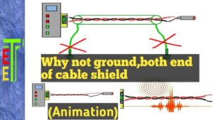
Why Cable Shielding Should Not Be Grounded at Both Ends
The primary reason that instrumentation cable shielding is not grounded at both ends of the wire is to prevent the formation of ground loops. When a shield is grounded at multiple points, it creates an alternate current path between different ground potentials, effectively turning the shield into a conductor for unwanted ground currents.
The Ground Loop Formation Process
When shielding is incorrectly grounded at both ends:
- Different ground potentials exist at each end of the cable run
- Current flows through the shield between these different ground points
- Magnetic fields are generated around the current-carrying shield
- Signal conductors are affected by these magnetic fields through inductive coupling
- Signal distortion and noise result from this electromagnetic interference
This is precisely why experienced engineers emphasize that to prevent unwanted ground loops, instrumentation cable shielding is not grounded at both ends of the wire.
Single-Point Grounding: The Correct Approach
The proper method for grounding instrumentation cable shields follows the single-point grounding principle:
- Ground the shield at one end only, typically at the receiving equipment
- Leave the shield floating (ungrounded) at the transmitting end
- Maintain shield continuity throughout the cable length
- Use insulated cable glands at the ungrounded end to prevent accidental grounding
This approach allows the shield to perform its EMI/RFI protection function while preventing ground loop formation.
Understanding Ground Potential Differences
Ground potential differences are the root cause of why instrumentation cable shielding is not grounded at both ends of the wire. These potential differences occur due to:
Electrical System Variations
- Voltage drops in building ground systems
- Differences in grounding electrode resistance at various locations
- Induced voltages from nearby power equipment
- Lightning-induced ground currents during storms
Physical Infrastructure Factors
- Soil resistivity variations affecting ground electrode performance
- Metallic piping systems creating alternate ground paths
- Building structural steel influencing ground distribution
- Concrete reinforcement affecting ground plane uniformity
Even small ground potential differences of just a few volts can cause significant problems when multiplied by the low impedance of a grounded shield, resulting in substantial ground loop currents.
Types of Instrumentation Cables and Proper Shielding Practices
Different types of instrumentation cables require specific approaches to shield grounding to prevent unwanted ground loops:
Twisted Pair Shielded Cables
Twisted pair instrumentation cables are commonly used for analog signal transmission:
- Individual shielded pairs: Each pair's shield grounded at receiving end only
- Overall shielded cables: Single shield grounded at one point for entire cable
- Combination shielding: Individual and overall shields require careful grounding strategy
The key principle remains that instrumentation cable shielding is not grounded at both ends of the wire, regardless of the shielding configuration.
Multi-Conductor Control Cables
Multi-conductor shielded cables used in control systems:
- Overall shield grounding: Single point at control panel or DCS rack
- Conductor isolation: Signal conductors remain isolated from shield
- Drain wire utilization: Bare copper drain wire provides easy shield access
- Terminal block grounding: Dedicated shield grounding terminals
Thermocouple Extension Cables
Thermocouple cables have special considerations:
- Temperature measurement accuracy depends on proper shield grounding
- Thermoelectric effects can be introduced by improper grounding
- Cold junction compensation requires careful attention to ground loops
- Extension vs. compensating cable selection affects grounding strategy
Communication and Data Cables
Digital communication cables require specific grounding approaches:
- Fieldbus cables (Foundation Fieldbus, PROFIBUS): Single-point shield grounding
- Ethernet cables: May use different grounding strategies depending on application
- Serial communication cables (RS-485, RS-232): Shield grounding critical for reliability
- Fiber optic hybrid cables: Metallic components require proper grounding
Common Mistakes in Shield Grounding
Understanding why instrumentation cable shielding is not grounded at both ends of the wire helps avoid these common installation errors:
Accidental Double Grounding
- Cable glands inadvertently grounding shields at both ends
- Conduit systems creating unintended ground paths
- Cable tray grounding accidentally connecting shields
- Equipment mounting creating multiple ground connections
Improper Termination Practices
- Stripped shield making contact with grounded surfaces
- Loose drain wires touching adjacent grounded components
- Inadequate insulation at the ungrounded end
- Poor workmanship during cable termination
System Design Oversights
- Lack of grounding documentation leading to confusion during installation
- Multiple technicians working without coordination on shield grounding
- Retrofit installations not considering existing grounding schemes
- Equipment changes affecting previously correct grounding
Application-Specific Grounding Guidelines
Different industrial applications have specific requirements for implementing the principle that instrumentation cable shielding is not grounded at both ends of the wire:
Process Control Systems
In process industries (chemical, petroleum, pharmaceutical):
- Analog signal loops (4-20mA): Shield grounded at control room end
- Smart transmitter communications: HART signals require proper shield grounding
- Safety instrumented systems: Critical for maintaining SIL ratings
- Hazardous area installations: Additional considerations for intrinsic safety
Power Plant Instrumentation
Nuclear and fossil power plants have stringent requirements:
- Safety-related systems: IEEE standards mandate specific grounding practices
- High electromagnetic interference: Multiple EMI sources require careful shielding
- Long cable runs: Increased susceptibility to ground potential differences
- Regulatory compliance: NRC and other agencies have specific requirements
Manufacturing and Automation
Industrial automation systems require reliable signal transmission:
- PLC analog inputs: Shield grounding affects measurement accuracy
- Variable frequency drives: High switching noise requires proper shielding
- Servo control systems: Encoder signals particularly sensitive to ground loops
- Machine integration: Multiple machines may create complex grounding challenges
Building Management Systems
Commercial building automation presents unique challenges:
- HVAC control systems: Temperature and pressure sensors require clean signals
- Fire safety systems: Life safety systems cannot tolerate signal interference
- Security systems: Access control and surveillance depend on reliable communications
- Energy management: Power monitoring requires accurate measurements
Testing and Verification Procedures
Proper testing confirms that instrumentation cable shielding is not grounded at both ends of the wire:
Pre-Installation Testing
- Cable continuity testing: Verify shield integrity before installation
- Insulation resistance testing: Confirm proper isolation between conductors and shield
- Ground fault testing: Ensure no unintended ground connections
- Shield resistance measurement: Document baseline shield resistance values
Post-Installation Verification
- Single-point grounding confirmation: Verify shield is grounded at one end only
- Ground potential measurement: Check for voltage differences between ground points
- Signal quality assessment: Monitor for noise and interference
- System performance validation: Confirm proper operation of connected equipment
Ongoing Maintenance Testing
- Periodic shield continuity checks: Detect deterioration over time
- Ground loop current monitoring: Identify developing problems
- Signal integrity analysis: Trend analysis of measurement quality
- Documentation updates: Maintain accurate records of grounding configurations
Troubleshooting Ground Loop Problems
When problems occur despite following the rule that instrumentation cable shielding is not grounded at both ends of the wire, systematic troubleshooting is required:
Identifying Ground Loop Symptoms
- Signal noise and interference: Random or systematic noise in measurements
- Equipment malfunctions: Unexplained control system behavior
- Communication failures: Data transmission errors or timeouts
- Measurement drift: Gradual changes in calibrated instruments
Diagnostic Procedures
- Ground potential mapping: Measure voltages between all ground points
- Current measurement: Check for unwanted currents in shields and grounds
- Signal analysis: Use oscilloscopes to characterize interference patterns
- Isolation testing: Temporarily disconnect suspected ground paths
Common Solutions
- Verify single-point grounding: Confirm shields are grounded at one end only
- Install signal isolators: Break ground loops electronically
- Improve grounding systems: Reduce ground potential differences
- Relocate sensitive equipment: Move away from interference sources
Advanced Grounding Techniques
Complex systems may require sophisticated approaches while maintaining the principle that instrumentation cable shielding is not grounded at both ends of the wire:
Hybrid Grounding Systems
- Combination of single-point and multi-point grounding: For different signal types
- Frequency-selective grounding: Using capacitors for high-frequency grounding
- Isolated ground systems: Separate grounds for sensitive equipment
- Star grounding configurations: Central grounding point for multiple circuits
Signal Isolation Methods
- Galvanic isolation: Transformer or optocoupler-based isolation
- Fiber optic transmission: Completely eliminating electrical connections
- Wireless communication: Reducing cable requirements entirely
- Balanced differential signals: Reducing ground loop sensitivity
Specialized Equipment
- Ground loop isolators: Active devices for breaking ground loops
- Common mode chokes: Filtering ground loop currents
- Isolation transformers: Providing galvanic isolation for power circuits
- Surge protective devices: Coordinated with grounding systems
Industry Standards and Best Practices
Various standards address the principle that instrumentation cable shielding is not grounded at both ends of the wire:
International Standards
- IEC 61000: Electromagnetic compatibility standards
- IEC 60364: Low-voltage electrical installations
- IEC 61158: Fieldbus standards for industrial communications
- IEC 62305: Protection against lightning
North American Standards
- IEEE 518: Guide for the installation of electrical equipment
- NFPA 70: National Electrical Code grounding requirements
- UL 508A: Industrial control panels standard
- ANSI/ISA-75: Control valve installation guidelines
Industry-Specific Guidelines
- API RP 551: Process measurement and control
- IEEE 979: Guide for substation grounding
- NEMA ICS: Industrial control system standards
- ISA-67: Nuclear power plant instrumentation
Economic Impact of Proper Shield Grounding
Understanding why instrumentation cable shielding is not grounded at both ends of the wire has significant economic implications:
Cost of Ground Loop Problems
- Equipment damage: Costly repairs and replacements
- Process downtime: Lost production and revenue
- Troubleshooting time: Engineering and technician labor costs
- System modifications: Retrofitting to correct grounding issues
Benefits of Proper Implementation
- Reduced maintenance: Fewer service calls and repairs
- Improved reliability: Better system uptime and availability
- Enhanced safety: Reduced risk of equipment failure and accidents
- Regulatory compliance: Avoiding fines and audit findings
Return on Investment
- Quality cable selection: Higher initial cost offset by longer service life
- Proper installation: Avoiding expensive retrofits and modifications
- Training investment: Skilled technicians prevent costly mistakes
- Documentation: Good records reduce troubleshooting time
Future Considerations in Shield Grounding
As technology evolves, the fundamental principle that instrumentation cable shielding is not grounded at both ends of the wire remains constant, but new considerations emerge:
Digital Transformation
- Industrial Internet of Things (IIoT): More sensitive digital communications
- Edge computing: Distributed processing requiring clean power and signals
- Wireless integration: Hybrid wired/wireless systems
- Cybersecurity: Physical layer security considerations
Environmental Factors
- Climate change impacts: More severe weather affecting grounding systems
- Aging infrastructure: Older facilities with deteriorating ground systems
- Renewable energy integration: New grounding challenges from distributed generation
- Smart grid implementation: Complex grounding in modern electrical systems
Regulatory Evolution
- Enhanced safety standards: Stricter requirements for process safety
- Environmental regulations: Reduced emissions requiring better control
- Cybersecurity standards: Physical security of control systems
- International harmonization: Consistent global standards
Conclusion: The Fundamental Importance of Single-Point Shield Grounding
The principle that to prevent unwanted ground loops, instrumentation cable shielding is not grounded at both ends of the wire represents one of the most fundamental concepts in electrical system design. This seemingly simple rule prevents countless problems and ensures reliable operation of critical industrial control and monitoring systems.
Proper implementation of single-point shield grounding requires understanding the underlying physics of ground loops, careful system design, skilled installation practices, and ongoing maintenance. While technology continues to evolve, this fundamental principle remains as relevant today as it was when first established.
Success in preventing ground loops through proper shield grounding ultimately depends on education, training, and discipline in following established best practices. By understanding why instrumentation cable shielding is not grounded at both ends of the wire, engineers and technicians can design and maintain systems that deliver reliable, accurate, and safe operation for decades to come.
Whether you're working on a new installation or troubleshooting existing problems, remember that proper shield grounding is not just a technical requirement—it's an investment in system reliability, safety, and long-term operational success.