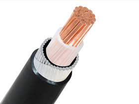
The 150mm² Single Core Aluminium Wire Armoured (AWA) Cable is designed for low voltage (0.6/1kV) power transmission in fixed installations. It is constructed with XLPE insulation and extruded PVC sheath, reinforced with aluminium wire armour to provide mechanical protection while avoiding magnetic interference—ideal for single-core applications. This cable is suitable for direct burial, cable ducting, or installation in industrial and utility environments.
Application
This cable is widely used for:
Power distribution networks
Underground installations in trenches or ducts
Indoor and outdoor fixed wiring
Power supply to buildings and substations
Applications requiring mechanical protection without inducing eddy currents (AWA for single core)
Auxiliary circuits and energy transmission where high reliability is required
Standards
BS 5467 – Armoured cables with thermosetting insulation
IEC/EN 60502-1 – Power cables with extruded insulation
IEC/EN 60228 – Conductors of insulated cables
Flame Retardant according to IEC/EN 60332-1-2
Optional fire performance: IEC 60332-3 series, BS 6724, BS 7211, and LSZH versions available
Construction
| Component | Description |
|---|---|
| Conductor | Plain aluminium, stranded, shaped (RE/SM/CC) |
| Insulation | Cross-linked polyethylene (XLPE), rated 90°C |
| Color Code | 1 Core: Red or Black (customizable) |
| Inner Sheath | Extruded PVC bedding with non-hygroscopic fillers |
| Armour | Aluminium Wire Armour (AWA) for single core cables |
| Outer Sheath | PVC Type ST2 (IEC 60502-1) or Type 9 (BS 5467); options: FR/Anti-termite etc. |
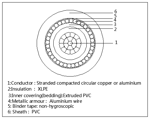
0.6/1KV Aluminium Wire Armoured AWA Cable CONSTRUCTION
Fire Performance Options
Cables can be manufactured with:
Flame Retardant Outer Sheath: IEC 60332-3-22/23/24
Low Smoke Zero Halogen (LSZH) compounds: IEC 60502-1, BS 6724
Special Sheaths available: FR PVC, Anti-rodent, Sunlight-resistant, Oil-resistant, LLDPE, HDPE, MDPE, or CPE
Advantages
Excellent electrical & mechanical performance
Lightweight and cost-effective compared to copper armoured cables
Non-magnetic armour suitable for single-core installations
Fire-safe options for critical infrastructure
Durable in harsh environmental conditions