Three Core Medium Voltage Unarmored Cable Construction
Application Overview
The Three Core 26/35kV XLPE Insulated Medium Voltage Unarmored Cable is designed for the transmission and distribution of electrical energy in medium voltage networks. It is ideal for use in power grids, industrial plants, and infrastructure projects where mechanical protection is not required, but electrical performance, flexibility, and reliability are critical.
This cable is suitable for both indoor and outdoor installation, including in ducts, trays, or directly buried (if protected), and can operate reliably under harsh environmental and chemical conditions due to its XLPE insulation and durable outer sheath.
Key Standards
-
IEC 60502-2 – Power cables with extruded insulation and their accessories for rated voltages from 1kV to 30kV
-
IEC 60228 – Conductors of insulated cables
-
IEC 60332-1/3 – Flame retardant performance
-
GB/T 12706.2 – Chinese standard for medium voltage cables
-
BS 6622, BS 5467 – British cable standards
-
IS 7098, IS 1554 – Indian standard equivalent
-
ICEA S-66-524 – North American specification for power cables
Cable Features
-
Voltage Rating: 26/35kV
-
Maximum Operating Temperature: 90°C (normal), up to 130°C (emergency), 250°C (short-circuit)
-
Short Circuit Rating: Up to 250°C (5 seconds)
-
Installation Temperature: ≥ 0°C
-
Minimum Bending Radius: 15 x cable diameter
-
Flame Retardant & Low Smoke options available (LSZH)
-
Halogen-free and UV resistant (optional)
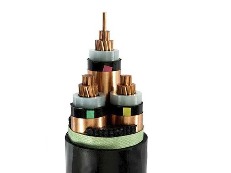
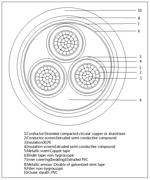
Construction Details
| Component | Description |
|---|---|
| Conductor | Stranded compacted circular copper or aluminum conductor (IEC 60228 Class 2) |
| Conductor Screen | Thermosetting extruded semi-conductive layer |
| Insulation | XLPE (Cross-linked Polyethylene), heat resistant up to 90°C |
| Insulation Screen | Thermosetting extruded semi-conductive layer |
| Metallic Screen | Copper tape or copper wires helically applied over each insulated core |
| Core Identification | Color tapes (Red, Yellow, Blue) applied between insulation screen and metallic screen |
| Assembly | Three screened cores laid up together with non-hygroscopic filler (if needed) |
| Binder | Wrapping tape (optional, depending on design) |
| Outer Sheath | PVC (ST2 to IEC 60502), PE, or LSZH as per customer requirement |
Advantages
-
Excellent Electrical Performance: Stable insulation properties under high voltage
-
Long Service Life: Resistance to thermal aging and chemical corrosion
-
Flexible and Easy to Install: Compact and lightweight compared to armored types
-
Cost-effective: No armor reduces cable weight and cost while still offering reliable MV performance
-
Safe Operation: Optional LSZH sheath provides low smoke and halogen-free safety
Typical Applications
-
Substations and switchgear connections
-
Power supply to large industrial plants
-
Infrastructure projects (tunnels, bridges, airports)
-
Renewable energy farms (wind/solar)
-
Urban and rural power distribution
Available Sizes and Configurations
We supply a wide range of sizes from 35mm² to 630mm², with either copper or aluminum conductors. Custom core marking, sheath color, and LSZH options available upon request.
📄 Need Technical Datasheet? Contact us to get detailed information including:
-
Conductor resistance
-
Capacitance and reactance
-
Current-carrying capacity
-
Voltage drop calculation
-
Overall cable dimensions and weight
Contact Us for Quotation and Support
Looking for a reliable supplier of 26/35kV medium voltage cables?
We offer:
✅ Competitive pricing
✅ OEM & export-ready packaging
✅ Fast delivery
✅ Technical customization based on your project