Application
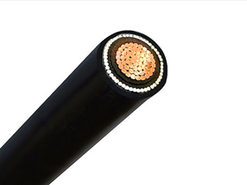
The 400mm² Single Core 0.6/1kV AWA Cable is designed for power and auxiliary fixed installations in electrical networks. It is suitable for indoor and outdoor use, underground systems, and cable ducts where mechanical protection is required. The Aluminium Wire Armour (AWA) offers protection against mechanical stress while maintaining non-magnetic properties, making it ideal for single-core installations in AC circuits to prevent eddy current losses.
Typical applications include:
-
Industrial power distribution
-
Utility networks
-
Renewable energy plants
-
Infrastructure and building services
Standards
Manufactured in accordance with:
-
BS 5467
-
IEC/EN 60502-1
-
IEC/EN 60228
-
Flame Retardant to IEC/EN 60332-1-2
Optional versions available in compliance with:
-
IEC 60332-3-22 / -23 / -24 for flame retardant sheaths
-
Low Smoke Zero Halogen (LSZH) to IEC 60502-1, BS 7211, or BS 6724
Construction
| Component | Description |
|---|---|
| Conductor | Plain aluminum, compacted circular or shaped stranded to IEC 60228 Class 2 (400mm² nominal size) |
| Insulation | XLPE (Cross-linked Polyethylene), rated 90°C |
| Core ID | 1 Core: Red or Black (customized colors available on request) |
| Inner Bedding | Extruded PVC bedding with non-hygroscopic fillers |
| Armour | Aluminium Wire Armour (AWA) for mechanical protection, specific for single-core applications |
| Outer Sheath | PVC Type ST2 (IEC 60502-1) or BS 5467 Type 9 |
| Optional Sheath Types | Fire-retardant, Anti-Termite, Anti-Rodent, UV-resistant, Oil-resistant, LSZH, HDPE, MDPE, etc. |
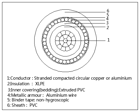
0.6/1KV Aluminium Wire Armoured AWA Cable CONSTRUCTION
Electrical & Thermal Characteristics
| Parameter | Value |
|---|---|
| Rated Voltage (U₀/U) | 0.6/1 kV |
| Maximum Conductor Temperature | +90°C (Normal operation) |
| Short-circuit Temperature | +250°C (for 5 seconds) |
| Minimum Installation Temperature | -5°C |
| Minimum Operating Temperature | -30°C |
Key Features
-
Excellent mechanical protection with AWA
-
Suitable for single-core AC installations without magnetic interference
-
Flame retardant to international standards
-
Available with customized sheath materials to suit harsh environments
-
Durable and long-lasting performance in underground and open-air installations