This three-core 21/35kV XLPE insulated unarmored cable is ideal for medium-voltage power transmission and distribution systems. It is widely used in utility networks, industrial facilities, and infrastructure projects that require:
-
High dielectric performance
-
Excellent thermal and mechanical strength
-
Chemical and corrosion resistance
-
Lightweight and easy-to-install construction
It is particularly suited for indoor or duct installations, where mechanical protection is not critical, but reliability and electrical performance are essential.
Standards
This cable complies with multiple international and national standards, including:
-
IEC 60502-2 – Power cables with extruded insulation for rated voltages from 6kV to 30kV
-
IEC 60228 – Conductors of insulated cables
-
IEC 60332 – Flame propagation
-
GB/T 12706.2-2008 – Chinese standard for medium voltage power cables
-
BS 6622, BS 5467 – British standard for MV cables
-
IS 1554, IS 7098 – Indian Standards
-
ICEA S-66-524 – North American standard for MV power cables
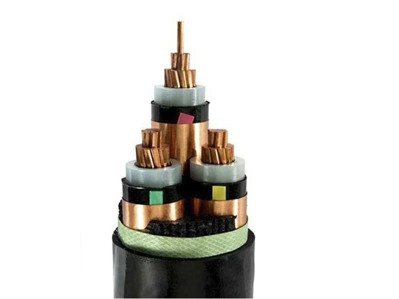
CONSTRUCTION
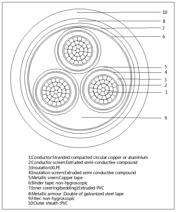
Three Core Medium Voltage Unarmored Cable Construction
| Component | Description |
|---|---|
| Conductor | Stranded compact circular copper or aluminum conductor, Class 2 per IEC 60228 |
| Conductor Screen | Extruded semi-conductive compound |
| Insulation | XLPE (cross-linked polyethylene), rated at 90°C |
| Insulation Screen | Extruded semi-conductive layer |
| Metallic Screen | Copper tape or concentric copper wires for each core |
| Core Identification | Color tapes (Red, Yellow, Blue) between insulation screen and metallic screen (customizable) |
| Assembly | Three screened cores laid up together with optional non-hygroscopic fillers |
| Inner Bedding | Extruded layer of compatible PVC or PE for core integrity |
| Outer Sheath | PVC type ST2 per IEC 60502, or optional PE / LSZH outer sheath for special environments |
Technical Characteristics
| Property | Value |
|---|---|
| Rated Voltage (Uo/U) | 21/35kV |
| Conductor Temperature | Max. 90°C during operation |
| Short-Circuit Temperature | Max. 250°C (for 5 seconds) |
| Test Voltage (5 min) | 50kV AC |
| Bending Radius (min.) | 15 × cable overall diameter |
| Flame Retardancy | IEC 60332 compliant |
| Sheath Options | PVC / PE / LSZH |
| Core Count | 3 cores (Red, Yellow, Blue) |
Advantages
-
XLPE insulation ensures excellent dielectric strength and thermal performance
-
Unarmored structure offers lightweight and flexible installation
-
Available with copper or aluminum conductors
-
Optional low smoke zero halogen (LSZH) sheath for safety-critical applications
-
Custom color code and marking available on request