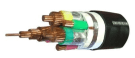
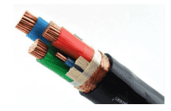
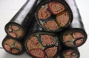
The structure of frequency conversion cables includes three insulated main conductor wires and three insulated neutral wires. Surrounding the main conductor wires and neutral wires are an inner wrapping layer, a copper tape layer, an outer wrapping layer, and an outer sheath layer in sequence, forming a 3+3 core structure. This design provides the cable with strong voltage impulse resistance, enabling it to withstand pulse voltages during high-speed and frequent frequency conversion, thereby offering excellent protection for frequency conversion electrical equipment.
Applications: Frequency conversion cables are primarily used for connecting frequency conversion power supplies to frequency conversion motors, as well as in power transmission and distribution lines with a rated voltage of 1KV and below for transmitting electrical energy. They are particularly suitable for industries such as paper manufacturing, metallurgy, metal processing, mining, railways, and food processing.
Operating Conditions:
- Rated voltage U0/U: 0.6/1KV
- Maximum allowable long-term operating temperature of the cable conductor: 90°C; maximum temperature during short circuits: 250°C
- Minimum ambient temperature for installation and laying: not less than 0°C; minimum ambient temperature for fixed laying: not less than -10°C
- Minimum allowable bending radius of the cable: not less than 15D (D = cable outer diameter, mm)
Performance:
- BPYJVP12R-TK and ZRBPYJVP12R-TK models are designed using soft stranded copper conductors that comply with the provisions of GB/T3956-1997, specifically Type 5.
- Cross-linked polyethylene insulation offers good temperature and weather resistance.
- Low transmission impedance and excellent electromagnetic compatibility.
- Low operating capacitance.
- Good anti-interference and low radiation performance.
- Symmetrical three-core cable structure design provides better transmission performance compared to four-core cables.
Common Models:
BPYJVP2: Copper conductor, cross-linked polyethylene insulation, polyvinyl chloride sheath, copper tape wrapping shielding frequency converter loop cable.
ZRBPYJVP2: Copper conductor, cross-linked polyethylene insulation, flame-retardant polyvinyl chloride sheath, copper tape wrapping shielding frequency converter loop cable.
BPYJVP12: Copper conductor, cross-linked polyethylene insulation, polyvinyl chloride sheath, copper tape wrapping with copper wire braid double shielding frequency converter loop cable.
ZRBPYJVP12: Copper conductor, cross-linked polyethylene insulation, flame-retardant polyvinyl chloride sheath, copper tape wrapping with copper wire braid double shielding frequency converter loop cable.
BPYJVPX12R: Copper conductor, cross-linked polyethylene insulation, polyvinyl chloride sheath, copper tape wrapping with tinned copper wire braid double shielding frequency converter loop cable.
ZRBPYJVPX12R: Copper conductor, cross-linked polyethylene insulation, flame-retardant polyvinyl chloride sheath, copper tape wrapping with tinned copper wire braid double shielding frequency converter loop cable.
Applications: Frequency conversion cables are primarily used for connecting frequency conversion power supplies to frequency conversion motors, as well as in power transmission and distribution lines with a rated voltage of 1KV and below for transmitting electrical energy. They are particularly suitable for industries such as paper manufacturing, metallurgy, metal processing, mining, railways, and food processing.
Cable specifications
| Model | Core Count | Nominal Cross-Section (mm²) |
|---|---|---|
| BPYJVTP2 | 1.5~240 | |
| ZRBPYJVTP2 | 1.5~240 | |
| BPYJVP12R | 3+3 | Main cores: 2.5–240, Auxiliary cores: 0.5–35 |
| BPYJVPX12R | 3+3 | Main cores: 2.5–240, Auxiliary cores: 0.5–35 |
| ZRBPYJVP12R | 3+3 | Main cores: 2.5–240, Auxiliary cores: 0.5–35 |
| ZRBPYJVPX12 | 3+3 | Main cores: 2.5–240, Auxiliary cores: 0.5–35 |
Specification Range:
Structural Design:
Cable Symmetry Design
For frequency conversion motor dedicated cables rated at 1.8/3kW and below, symmetric 3+1-core and 4-core cables can only be used as input cables for the main power supply, but it is preferable to use symmetric structured cables. Cables connecting frequency converters to frequency conversion motors must adopt a symmetric cable structure, which includes 3-core and 3+3-core types. The 3+3-core cable structure involves decomposing the fourth core (neutral core) among the three large and one small four-core insulated conductors into three smaller insulated conductors, and symmetrically cabling these three large and three small conductors. For frequency conversion motor dedicated cables rated at 6/10kV, this cable structure differs from that of ordinary 6/10kV power cables. Ordinary power cables cable three insulated conductors after copper tape shielding, whereas frequency conversion motor dedicated cables use copper wire and copper tape shielding, followed by extruded phase-separated sheaths, and then symmetrically cabled. The symmetric cable structure, due to the interchangeability of conductors, offers better electromagnetic compatibility, plays a certain role in suppressing electromagnetic interference, cancels out odd-order frequencies in higher harmonics, enhances the anti-interference performance of frequency conversion motor dedicated cables, and reduces electromagnetic radiation in the entire system.Shielding Structure Design
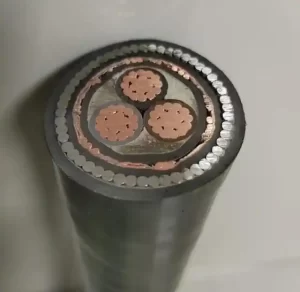
The shielding for frequency conversion motor dedicated cables rated at 1.8/3kV and below generally adopts overall shielding. For 6/10kV frequency conversion motor dedicated cables, the shielding consists of phase-separated shielding and overall shielding. Phase-separated shielding typically uses copper tape shielding or a combination of copper wire and copper tape shielding. The overall shielding structure can adopt a combination of copper wire and copper tape shielding, copper wire braiding shielding, copper tape shielding, or copper wire braiding with copper tape shielding. The shielding layer's cross-sectional area is in a certain proportion to the main conductor's cross-sectional area. This structured shielded cable can resist electromagnetic induction, poor grounding, and power line conduction interference, reduce inductance, and prevent excessive induced electromotive force. The shielding layer not only suppresses electromagnetic wave emission but also serves as a channel for short-circuit currents, providing protection for the neutral core. For 6/10kV frequency conversion motor dedicated cables, considering the frequent radial external forces acting on the cables during use, a galvanized steel tape armor layer is added outside the cable shielding layer (with an isolation sleeve between the shielding layer and the steel tape armor layer). The steel tape armor primarily acts as a radial mechanical protection layer for the cable and also serves as an additional overall shielding, especially when combined with copper wire and copper tape shielding. The use of two different shielding materials, steel tape armor and copper wire/tape shielding, provides complementary effects in electromagnetic wave shielding, resulting in better shielding performance.
Cable Electrical Performance Design
The electrical performance of frequency conversion motor dedicated cables rated at 1.8/3kV and below is designed in accordance with the GB/T12706.2002 standard. For 6/10kV frequency conversion motor dedicated cables, in addition to meeting the GBT/l2706.2002 standard, additional electrical performance requirements such as capacitance and inductance have been added. The electrical performance parameters of the cables are determined based on the actual usage conditions of frequency conversion motor dedicated cables and with reference to GB/T 12706.2002.